
My sister’s birthday is coming up so I decided to make her something personal that you can’t easily get in a store. And because it’s me, of course it has to have flashing lights and at least one microcontroller in it. In this post, I’ll detail how I built and programmed a device using a generic LCD screen module, an Atmega328p, and other simple parts.
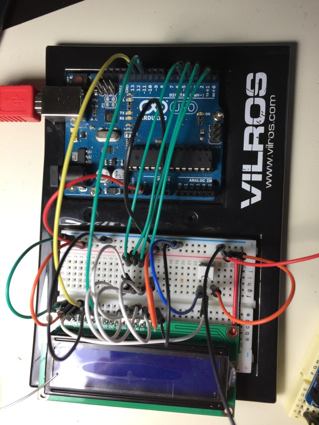
Before soldering anything together, I always try to prototype on a breadboard. Because I hadn’t used these LCD modules before this project, I figured out how to interface with them. I got them for next to nothing on eBay but was fairly sure they had an arduino library floating around somewhere. And sure enough, there absolutely was! The LiquidCrystal library makes it super simple to enter text, and easily lets you create custom characters. I based my code off the CustomCharacter example, and used the “man” and the “heart” icons.
The LCD itself connects without too much trouble; power and ground for the LCD, and power/ground for the LED with current limiting resistor for the backlight. Four data pins and two more for Reset and Enable, and then you’re good to go to use the LCD library. The contrast is adjusted with a potentiometer tied to the VO pin. I’ll definitely be using these cheap displays in future projects, as long as I have six pins available and need a low-res display.
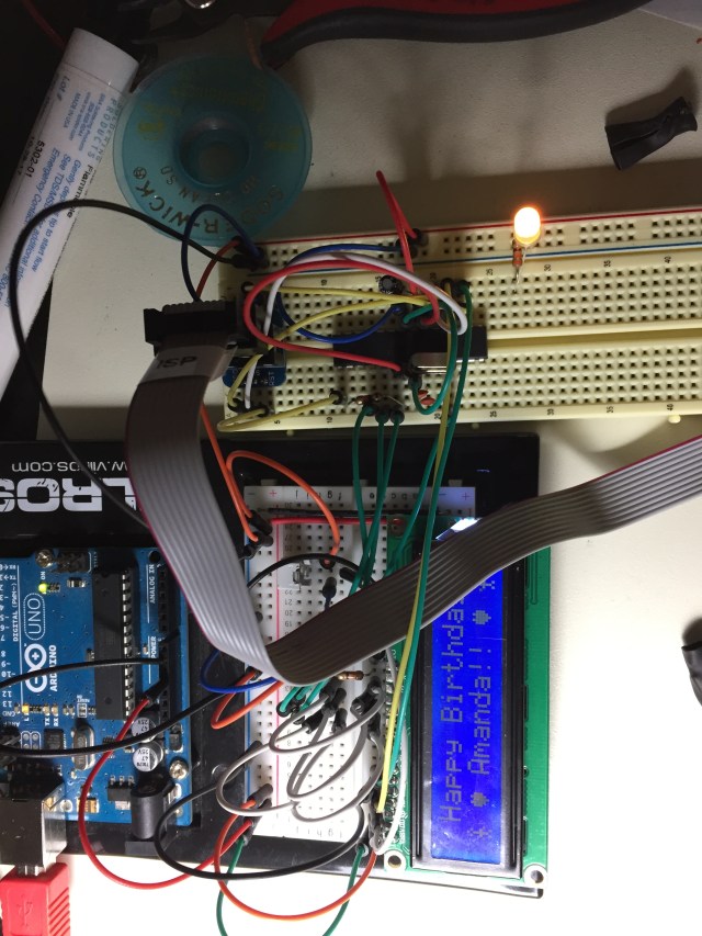
For the animation itself, I made it so two stick figures would walk on screen, carrying a line of hearts. Then the message “Happy Birthday Amanda” shows after that, first in all caps and then with normal capitalization. See the end of this post for a demonstration.
You can find my code at the following link: https://github.com/tedmyers/Bday_LCD
(link opens in a new window/tab)
After making sure I could properly interface with the LCD and animating everything, I moved on to programming and testing the Atmega328. I set it up on a breadboard, connected the appropriate power and ground pins, pullup on reset, and attached a 16MHz crystal oscillator.
Next it was time to program the chip. If I wanted to, I could’ve just uploaded my sketch by placing it in my Arduino Uno (after loading a bootloader onto the chip) but where would be the fun in that?
I used a 6-pin ICSP breadboard breakout, the Bus Pirate v3.6, and a custom 5×2 socket cable and adapters from 5×2 to 3×2 at the end. I had some trouble here and eventually figured out that the 5×2 to 3×2 ICSP adapter board I ordered from Amazon a while back was faulty; the solder hadn’t properly flowed on the CLK pin and was causing my programming to fail. Luckily I was able to fix this easily with a touch of the soldering iron after figuring out the problem.
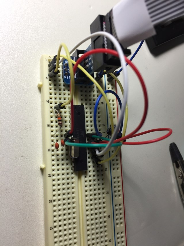
Here’s a clearer image of the programming setup for the Atmega328
Next I found the .hex file that Arduino generated and uploaded it with the following command:
avrdude -p m328 -P /dev/cu.usbserial-AL008K5E -c buspirate -U flash:w:Bday_LCD_Code.cpp.hex
And now the animation was playing , but not quite right; it was much too slow. The fuse bits were still set to prescale the clock by a factor of eight. I then reprogrammed the fuses with the following command:
avrdude -p m328 -P /dev/cu.usbserial-AL008K5E -c buspirate -U lfuse:w:0xff:m -U hfuse:w:0xde:m -U efuse:w:0x05:m
And everything worked. On a side note, avrdude seemed to be displaying the incorrect high/extended fuse bytes. I’m not sure why this was the case, but either way the clock was no longer being prescaled and my animation was working as designed.
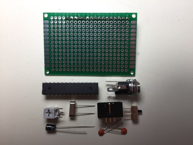
Now that everything was working on a breadboard, I soldered everything up. I soldered the LCD module onto a protoboard and lined up everything I needed. You can see each component in the picture below:
- Atmega328 microcontroller
- 16MHz crystal oscillator
- 2x 22pF capacitors
- 0.1uF capacitor
- 10uF capacitor
- 10k Potentiometer
- Power Switch (SPDT)
- DC Power jack
In the end I decided to opt out of the ICSP header, as I wasn’t planning on reprogramming the chip after the initial time. As a compromise, I used a dip-socket so I could pop it out and reprogram if necessary.
I decided to “slot” the LCD on top of the main circuit. This way the LCD screen is front and foremost, and the final product doesn’t end up too large. I was planning on shipping this across the country after all, and don’t need a gigantic PCB. I also like trying to fit everything in a small space, and think I did it fairly well in the end.
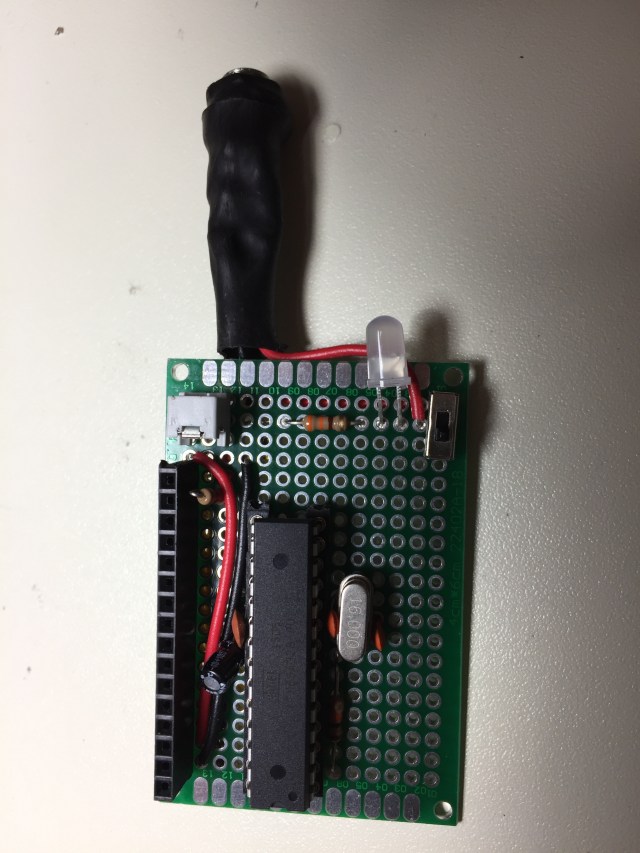
Here you can see the finished product of a few hours of soldering. I decided to also add a power indicator LED, and I used the slow color fading “smart” LEDs from adafruit (https://www.adafruit.com/product/679) to both indicate that the power switch has been turned on, and to add an interesting backlight/underglow effect.
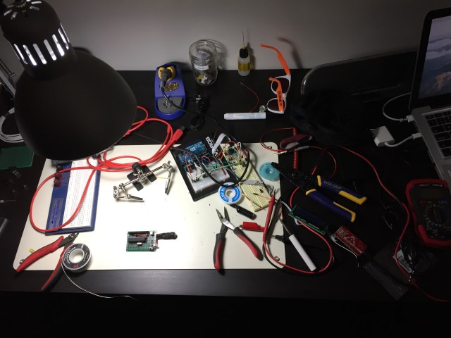
Here you can see how messy my desk gets when working on a project.
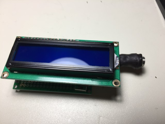
And finally, the finished product! I had to debug it a little due to human error in some solder joints, but otherwise this project went pretty smoothly! It’s always nice when you can catch your flaws soon enough to make something cool without too much hassle; I’d definitely recommend testing and prototyping before undertaking any project.
Now sit back, relax, and enjoy the video of it in action!
Video:
After all this work, I packed it up in a box with a 5V power adapter that plugs into the power jack, taped it up, and shipped it off to my sister.
I hope you enjoyed hearing about this little project I made for my sister, and hope you remember to show appreciation for your family and friends!
