Making a Flash Trigger using Arduino code on an ATtiny85


Introduction
In this post I’ll go over how I created a high-speed flash triggering device, as well as detailing how it works. Since creating this project I have learned a lot more about electronics and using the Arduino platform, and thus there parts of this device I would do differently now. But even with the mistakes I made then, this project was a great way to get me into prototyping my own devices that stand alone and perform a useful function.
What is it?
First, lets go over what it does: When a laser is crossed, an external camera flash is triggered.
The flash can also be triggered by a microphone, which will cause the flash to fire once a certain noise threshold has been reached.
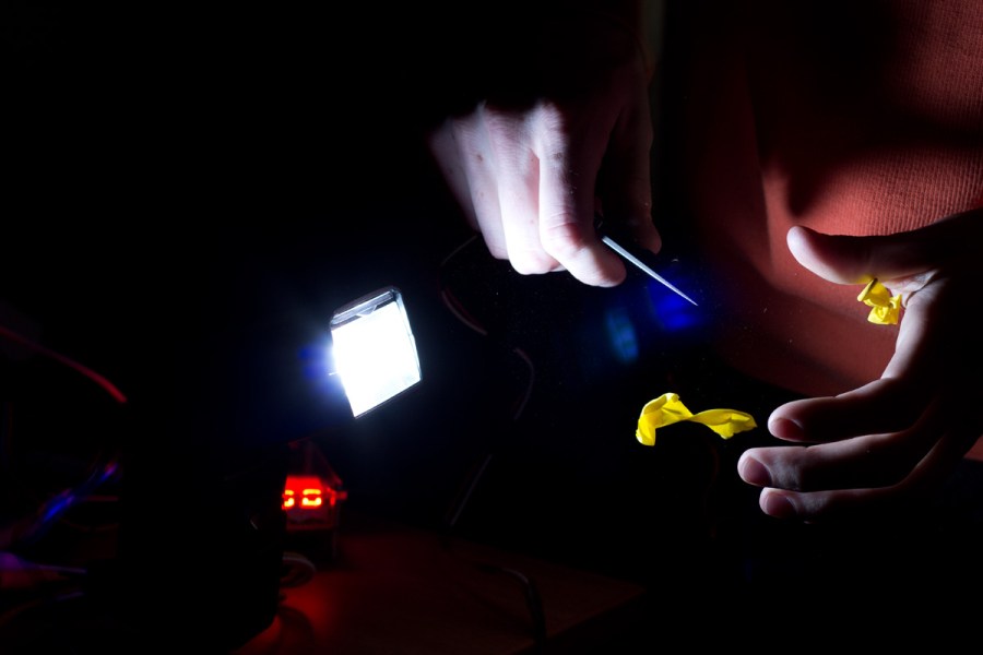
So, why is this useful? A controlled flash makes it a lot easier to get consistent high speed photos. Think of this example: you want to capture a falling milk droplet right as it hits a surface; the idea is that the laser and sensor are set up so the droplet will cross the laser and cause the flash to fire, causing light to hit the camera’s sensor only at the instant that the laser is crossed.
In my device, I also added a display and adjustment knob so I can add a very specific delay, which is useful when you want the flash to fire later, so I can more easily capture specific instants after the droplet splashes up again. This allows for more flexibility in the laser placement.
Here’s a photo I took with the same scenario that I just described:

Note: The delay was actually one of my problems: due to the way my code ran, it caused too much delay. This is because the main loop of my program took too much time to run, as it would read the analog values of various pins on my microcontroller and output the delay to a screen. Were I to do this project again on the same platform, I would use external interrupts which allow a much faster execution time, as they only execute their relevant code the instant after the signal is received and don’t have to take time out of the main code loop to poll a sensor.
Now that you know the basics of what it does, lets go over how it works.
How it Works
I started by using my Arduino Uno to make an external camera flash fire. It’s a fairly simple procedure to make an external camera flash fire with an arduino. First, lets go over how the flash triggering works. Most external flashes have a port on the side, to plug in what is called the PC sync cable. You make the flash fire by completing the circuit between two terminals using this cable. This is also possible on most flashes through the hotshoe mount, which allows for proper flash firing when attached to a camera.
Because there’s a lot of current running through these wires for a short period of time, we need to isolate it from the arduino circuit. I used a photocoupler, which has a small light-emitting diode and a sensor in it. This means that when a voltage is applied through two of the pins, current can freely flow between two other pins, allowing us to control current without directly allowing it to flow through our arduino circuit (and thus isolating it). Interestingly enough, there is a small LED inside the DIP package, meaning a current-limiting resistor needs to be placed in series with the input pins. It is the lighting of this LED which allows the current to flow on the other two pins.
Here’s a demonstration of the photocoupler in action, allowing an LED to be lit up.
(Shot of LED lighting up when the two pins are applied current, or a graphic showing current flow with arrows)
So all we need to do to make a flash fire is use our arduino to create a +5V signal on one of its pins, place a resistor in series so it doesn’t burn out the photocoupler, and connect the two wires coming from the flash to the other side of the photocoupler.
Now that the arduino can cause our flash to fire, we need to find a way to trigger the arduino’s command. I chose to use a laser and a photoresistor to make the flash fire at the instant the light from the laser ceases to shine on the photoresistor.
An arduino can only directly measure voltage, not resistance; therefore we need to set up a voltage divider with another resistor connected in series to the photoresistor for the arduino to obtain useful data about light. This way, when the photoresistor changes its resistance, we can quantitatively measure it. And of course, we’ll need a laser. You can get cheap red lasers nearly anywhere these days. In fact, I ordered ten little 5V modules for less than five dollars. I soldered one of these onto some longer wires and a tripod mount by cutting ¼” threaded metal couplers in half and taping them on.
You could do this, or use any other bright light source, as long as it will constantly stay on the photoresistor until you want the flash to be triggered. Now that we can get data about light hitting the sensor, we’re ready to start with our program.
Programming and the ATtiny

I won’t go too far into the code I wrote, but I’ll try to touch on everything I needed to make the device work.
First, I prototyped my device using an Arduino Uno. When I was making this, (Winter of 2014), I had only been working with electronics and the Arduino platform for maybe a month or two, when I found time during school. It was during winter break that I was really able to dig into it more and make a larger project such as this. I also continue to be amazed by the support and communities around Arduino and how easy it is to set up a project and find answers to any questions that pop up while working on electronics.
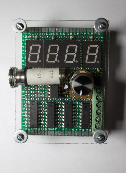
One thing that I wanted to do with this project was have a nice, easy-to-read display. I had ordered a bunch of 7-segment displays online for pretty cheap and I like the look of them so I thought I’d go with that. Because you need to be able to control a lot of outputs to light the LEDs inside the display, I used shift registers (74HC595) to control the display.

I didn’t know about shift registers before making this, and I think they’re a really interesting way to expand the number of pins you can control by using only three outputs on a microcontroller. It works by having a communication protocol that uses three pins: one as a clock, to tell the register when to store each bit; one to actually send the data, as a digital 0 or 1 by sending a 0V or 5V signal; and the last one as a “latch”, to tell the shift register to output the data, causing it to create a digital signal on its eight output pins, corresponding to the data that was sequentially sent to its data pin.
Here’s a video with more information about shift registers, if you want to learn more: https://youtu.be/6BLj9Ak2Djs
With the help of four shift registers, I was able to control the values displayed on four seven-segment displays.
After figuring out how to use my displays, I just had to program and put it together. I used a 10kOhm potentiometer to select how many milliseconds of delay time I wanted. I am able to do this because the Arduino has an ADC (analog to digital converter), so it is easy to map its voltage to a 0-1000 millisecond delay.
My code allows for selecting a sound mode, or a laser mode. Each reads an analog value, but this time from a pin which is connected to either a microphone unit or the photoresistor mentioned earlier in its voltage divider setup. When one of these crosses a certain voltage threshold (which was fine-tuned by me earlier), it sends a signal to the photocoupler, allowing current to flow through the flash.
So generally, that’s how it works. Power, the sensor, and the flash unit are connected with screw terminals; there are four 7-segment displays which display the amount of delay; and the main input is a potentiometer that you turn to adjust values and enter the menu to change settings.
Next, we need to load the code onto an ATtiny. Luckily, there is a fairly easy way to do this with an Arduino Uno. With only a 10 micro-Farad capacitor and an Arduino, the serial data from your computer can be loaded onto the very small ATtiny chip. This website, http://highlowtech.org/?p=1695, has complete details on how to do it. With the new Arduino IDE, you can even download their libraries very easily, and can easily run the Uno as an ISP.
This is a key step that allowed me to move past the need to connect my Uno each time and let me make a stand-alone unit.
Construction
It was a lot of work soldering everything all together, especially with every connection I needed for the seven-segment displays. I added a 1/4 inch audio jack, which connects to the flash via the PC sync cable. Next, everything was wired up to an 8-pin IC socket adapter, where I could plug in the ATtiny85. Four shift registers were added, the potentiometer, and the screw terminals.
Here’s some images showing my planning process and the wires being soldered into place:


After all that work, I finally had a working product! I decided to also make a nice plexiglass housing, to make it a little more robust and create a more “finished” look.


Materials
- 4x 74HC595 Shift Registers
- 4x Common Cathode 7-segment displays with “.”
- 5x 330 ohm resistors (I used 1/6W)
- 10k Potentiometer and knob
- female ¼” female threaded connector
- ATtiny85 and 8-Pin IC holder
- Screw terminals
- Various colors of ~22 gauge insulated wire
- 1-2x 10uF capacitors
- 3x 0.1uF capacitors
- 1x Photocoupler (I used a 4-pin)
- Laser Modules
- Optical Resistor and 10k Ohm resistor
- Double-sided Prototyping Board
Optional (for housing)
- 4x Machine screws
- 4x Nuts
- 4x Washers
- 4x Lock washers
- Aluminium Tubing
Done!
Conclusion
And finally, I have a finished product! As I mentioned earlier, there are a few things I would do differently if I were to make this again, but I am very happy with what I made. I went from very little experience with electronics to making a finished product with a flashy screen, working input, and ability to improve my photography. I hope you have enjoyed learning about what I have made, and I’ll leave you with some photos that I have taken with this device.
Photos


